-40%
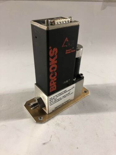
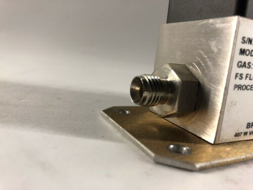
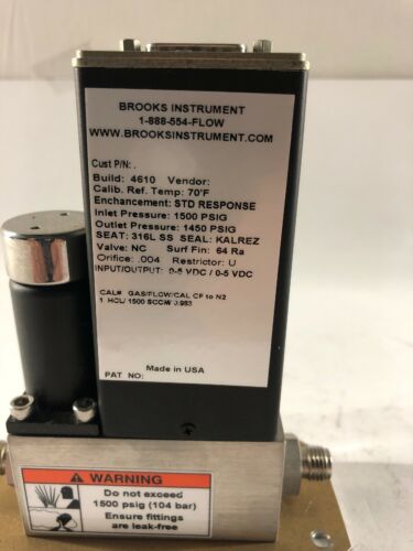
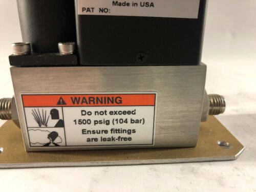
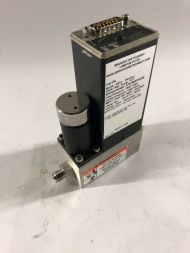
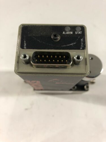
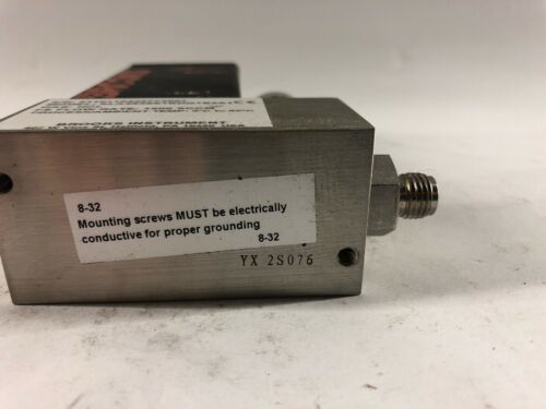
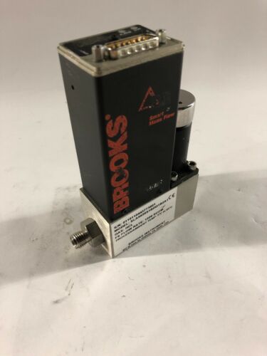
BROOKS SLA5850S1BDG1B2A1 DELTA II SMART MASS FLOW CONTROLLER
$ 264
- Description
- Size Guide
Description
BROOKS DELTA IISMART MASS FLOW CONTROLLER
Model:
SLA5850S1BDG1B2A1
Gas:
HCL
FS Flow Rate:
1500 SCCM
We have many MFC's to choose from. Please see our Ebay store (Krucial Products) for more to choose from.
INTRODUCTION To MFC's
MFCs are used to measure and control the flow of gasses in a process. The overall flow rate is an important consideration.
Some processes require very small flows usually specified in standard cubic centimeters per minute (SCCM).
Higher flows are typically given in standard liters per minute (SLPM) or standard cubic feet per minute (SCFM).
Many manufacturers make devices able to measure flows of 200 sccm up to 30 slpm.
The same body size can be used for this wide range of flows; however, the internal components are changed to give a more precise flow range.
Typically, once you choose a maximum flow, you are able to measure and control down from there a certain amount.
Having a 10 to 1 turndown is common. Being able to control to a 50:1 or even 100:1 is available from some of the leading manufactures.
Setting the maximum flow to something very small like 10 sccm or even 3 sccm and then being able to measure and control from that point down to 2% is remarkable, but is standard for some.
Once the desired flow is more than 30 slpm (or 1 scfm), usually the physical size of the MFC body changes a bit.
This allows greater flow as there are larger passageways inside the device. Flows to 100 slpm or 200 slpm are typical in this arrangement.
Once the flow gets higher than that, the body size really jumps and this allows flows up to 2500 slpm to be controlled or 9000 slpm flows to be measured (without a control valve).
The gas itself is an important consideration. Are you flowing one of the simple, common gasses such as air, oxygen, nitrogen, helium, hydrogen, argon, CO or CO2?
If so, a simple design of the MFC can be used. If your gas is very dangerous, you may be required to treat it differently.
If it is susceptible to contamination, such as reacting with moisture, the interior of the MFC may be polished and the connections changed from screwed or compressed fitting to higher purity type connections such as VCR or VCO which utilize metal seals and are considered when high and ultra high purity gases are being used.
If the process is being run at a positive pressure, the design of the MFC is such that it can contain that pressure.
Some MFCs are limited to 100 psi or 500 psi maximum working pressures. Industrial MFCs are usually standard at 1500 psi (100 bar) and can be made to withstand 4500 psi (300 bar) pressure sometimes found in catalyst research, hydrogenation of food or drugs, or many petrochemical processes.
On the other hand, if your process operates under vacuum, the design of the MFC has to be adjusted accordingly. Gases behave differently at positive pressures than they do under high vacuum and calibrating an MFC for vacuum service is a precise process.
Temperatures of the gases are to be considered. Usually the gases are measured and controlled at relatively mild temperatures and elevated after the MFC if high temperatures are required in the process.
There are temperature limits inside an MFC due to the measuring technology which utilizes the thermal properties of the gas to determine the flow. So, typically, 140-160°F is the working limit for gasses in MFCs.
When asked about accuracy, many applications require the most accurate system available. However some processes are not precise and a less accurate device can be used.
Sometimes accuracy is not as important as repeatability. You must first understand the difference between percent of full scale accuracy statements and percent of rate accuracy statements.
They mean the same thing only when the device is operating at 100 percent of its rated capacity.
If you ask the MFC to control the gas flow to a lower set point, the amount of error varies in different MFC designs.
Older, analog MFCs typically have accuracy statements such as +/- 1 % of full scale.
This means a 100 sccm MFC would have an acceptable error of 1 sccm at any flow. If the flow were to be set at 50%, a 1% FS error would actually be 2% of that rate.
If the flow were at 20%, the same 1 sccm deviation would now be a 5% error. Devices with error statements given in % fs are not as accurate as those given in % rate.
Let us look at a device with a stated accuracy of +/- 1% of rate from 100% flow down to 20% flow and +/- 0.2% of full scale below 20 percent flow.
Using the same example, if the 100 sccm MFC were flowing at 50% the maximum error would be ½ sccm or 1 % of rate.
If the flow were set at 20%, the error would be 0.2 sccm or 1% of that rate.
ABSTRACT
There are four main considerations to evaluate in order to specify a Thermal Mass Flow Controller (MFC) for your application.
Flow range, gas conditions, desired accuracy, and communications are all important constraints.
There are a five additional considerations including interior finish for high and ultra high purity applications, materials used in the flow path, the environment such as installations near furnaces or some sort of NEMA rating, mounting attitude such as vertical flow up, and serviceability.
Specifications
PERFORMANCE CHARACTERISTICS:
Flow Ranges
Models SLA5850/SLA5860
Any FS range from 0-3 ccm to 0-30 lpm (N
2
eq.)
*Up to 0-50 lpm (N
2
eq.) w/coplanar valve option
Models SLA5851/SLA5861
Any FS range from 20-100 lpm (N
2
eq.)
Up to 200 lpm H
2
flows possible
Models SLA5853/SLA5863
Any FS range from 100-2500 lpm (N
2
eq.).
Control Range
Turndown 50:1
Turndown 100:1 with Coplanar valve option
(For any FS range from 1-50 lpm (N
2
eq.)
Accuracy
(N
2
eq. at calibration conditions)
.
±1.0% of rate (20% - 100% FS)
±0.2% FS (below 20% FS) up to 1100 lpm.
(Optional:
±0.7% of rate ±0.2% FS ("S-Series") up to
1100 lpm.
Flow ranges above 1100 lpm and up to 2500 lpm
±1.0% of full scale
.
Repeatability
±0.20% of rate.
Settling Time/Response Time
< 1 second to within ±2% FS of final value for a
0-100% command step (better on request)
for flow rates up to 100 lpm (N
2
eq.).
< 3 seconds to within ±2% FS of final value for a
0-100% command step (better on request)
for flow rates greater than 100 lpm (N
2
eq.)
up to 2500
lpm (N
2
eq.).
Sensitivity to Mounting Attitude
<0.2% FS maximum deviation from specified accuracy,
after rezeroing.
